HOMOKINETIC JOINT
Find out the details →

RELATED COMPONENTS
RELATED APPLICATIONS
TECHNICAL FEATURES
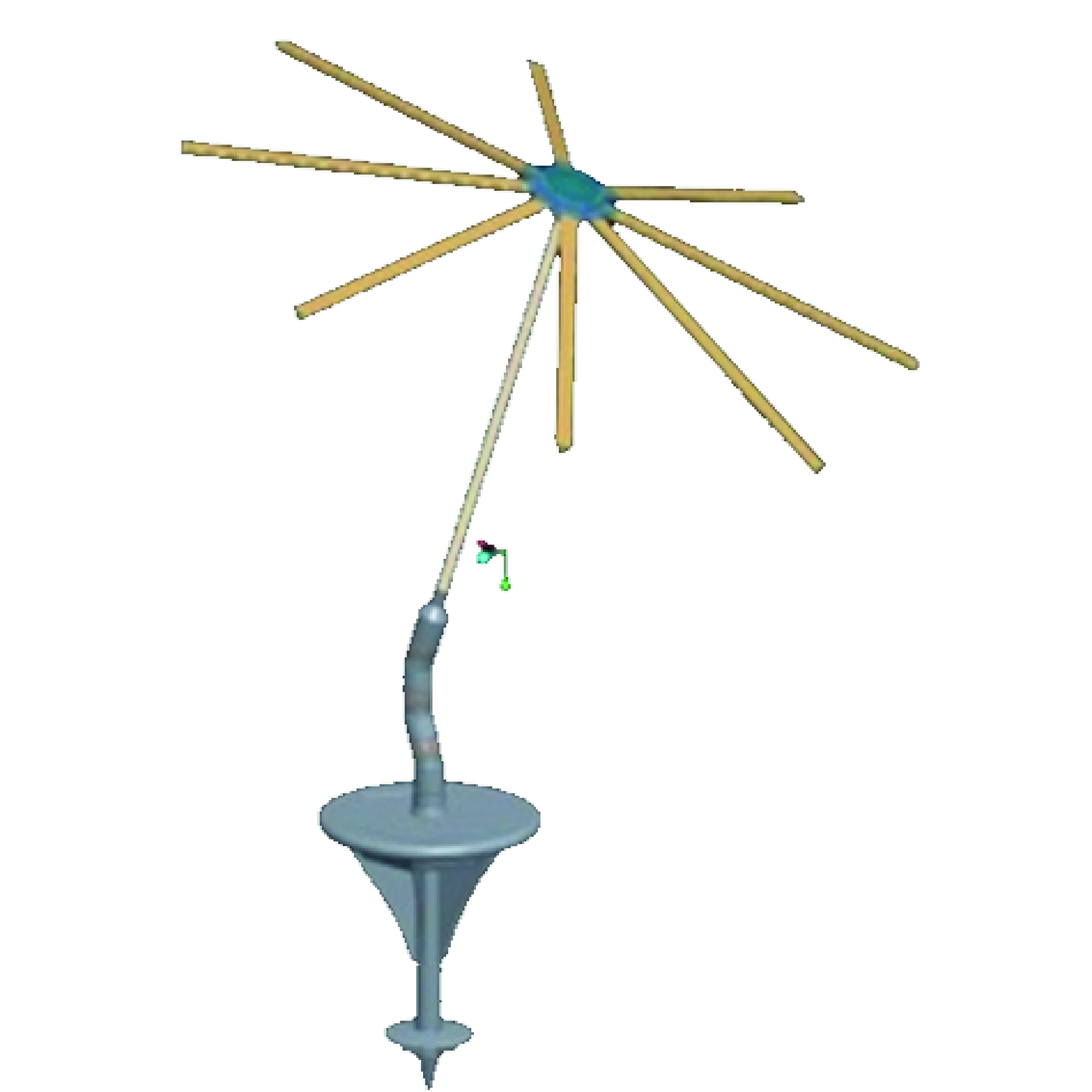
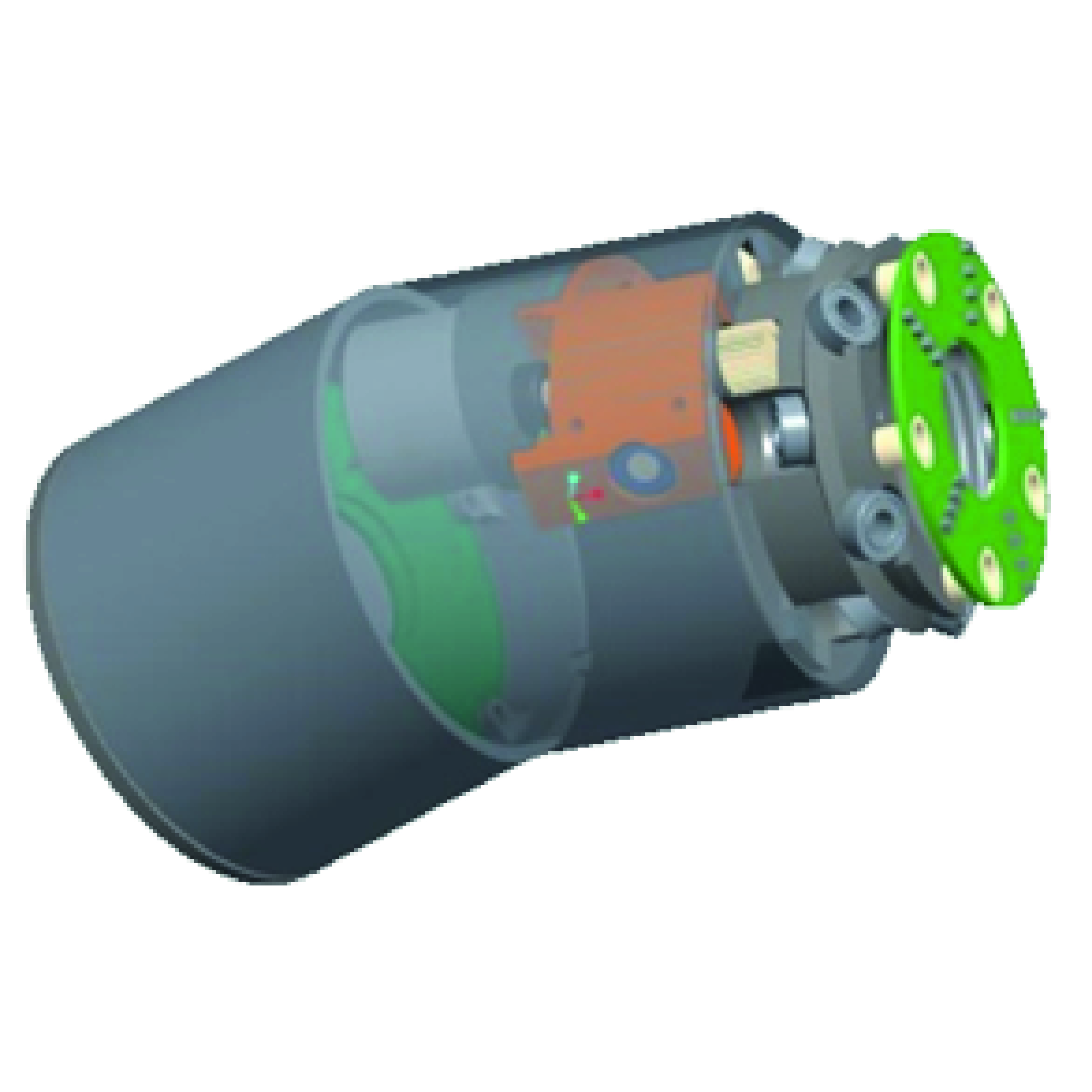
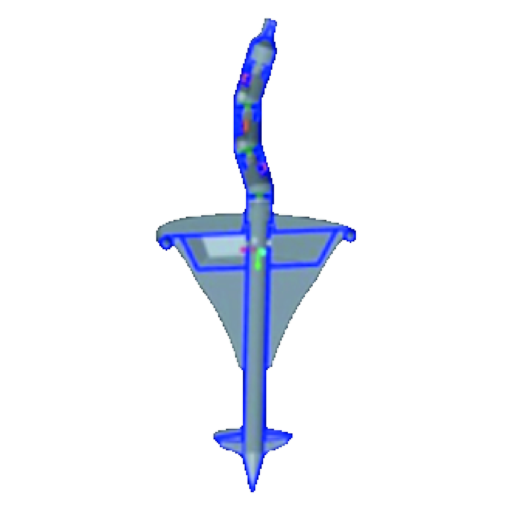
The blocked constant velocity joint is a component initially designed to allow the tilting of a pole, typically the one that holds the canvas of an umbrella. However, the applications of this joint are numerous, just think of all the low-cost manipulators and robotics. This joint, despite having only one degree of freedom, can be linked with other identical joints and consequently obtain all the degrees of freedom desired. The concatenation occurs through a predetermined angle coupling with the next node and so on. Depending on the rotation between the two joints, a displacement is generated between the two ends. Increasing the number of nodes increases the displacement until it reaches an angle of 360° or even more. The basic idea recalls the movement of the caterpillar, which is also made up of many sections with a limited degree of freedom but which, united together, allow the insect to move freely. The joint is designed for different angles and for different loads. It is made in two different diameters: 75mm and 90mm, but the dimensions can be of any diameter and length. The control and movement electronics are located internally and communicate with the adjacent joint or with the base via a digital bus. The electrical connection is guaranteed by means of brush contacts which favor a rotation of 360° and more. In the center there is a cavity that allows to run cables, conduits, etc... around which the joint rotates without causing twisting. A control electronics unit external to the movement system but which knows the mechanical dimensions of the equipment, controls the rotation of all the nodes until the desired curvature is obtained and such as to bring the two ends into the desired/requested positions. The rotation model calculates a curve and then begins the movement so as to bring the curve to the center of all the nodes. When the matching of the nodes is completed, you can redraw a new curve and repeat the matching. By repeating this cycle without interruptions, continuous movement and the desired tilting are obtained. The speed of movement of one end relative to the other depends on how the approach curve is modeled.
TECHNICAL FEATURES
The blocked constant velocity joint is a component initially designed to allow the tilting of a pole, typically the one that holds the canvas of an umbrella. However, the applications of this joint are numerous, just think of all the low-cost manipulators and robotics. This joint, despite having only one degree of freedom, can be linked with other identical joints and consequently obtain all the degrees of freedom desired. The concatenation occurs through a predetermined angle coupling with the next node and so on. Depending on the rotation between the two joints, a displacement is generated between the two ends. Increasing the number of nodes increases the displacement until it reaches an angle of 360° or even more. The basic idea recalls the movement of the caterpillar, which is also made up of many sections with a limited degree of freedom but which, united together, allow the insect to move freely. The joint is designed for different angles and for different loads. It is made in two different diameters: 75mm and 90mm, but the dimensions can be of any diameter and length. The control and movement electronics are located internally and communicate with the adjacent joint or with the base via a digital bus. The electrical connection is guaranteed by means of brush contacts which favor a rotation of 360° and more. In the center there is a cavity that allows to run cables, conduits, etc... around which the joint rotates without causing twisting. A control electronics unit external to the movement system but which knows the mechanical dimensions of the equipment, controls the rotation of all the nodes until the desired curvature is obtained and such as to bring the two ends into the desired/requested positions. The rotation model calculates a curve and then begins the movement so as to bring the curve to the center of all the nodes. When the matching of the nodes is completed, you can redraw a new curve and repeat the matching. By repeating this cycle without interruptions, continuous movement and the desired tilting are obtained. The speed of movement of one end relative to the other depends on how the approach curve is modeled.
RELATED COMPONENTS
RELATED APPLICATIONS
IMAGES & VIDEOS
Contact us
Fill the form
Do you want to know more or want to start a form of collaboration with FREE ENERGY TECHNOLOGIES S.r.l., write to one of the following emails.
We are available to evaluate your requests and bring your needs to life by applying our technology.
Copyright 2023 FREE ENERGY All Rights Reserved 2023 | Policy Privacy | Cookie Policy
Website: Galileo146
FOLLOW US ON